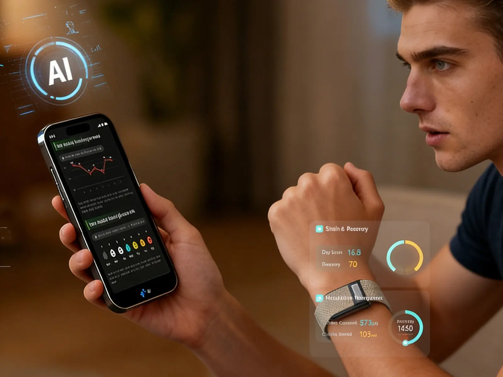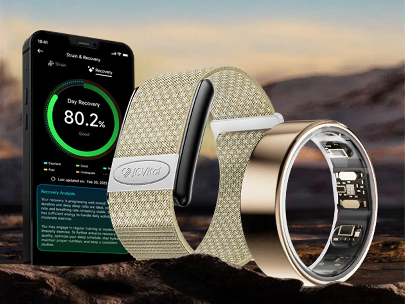
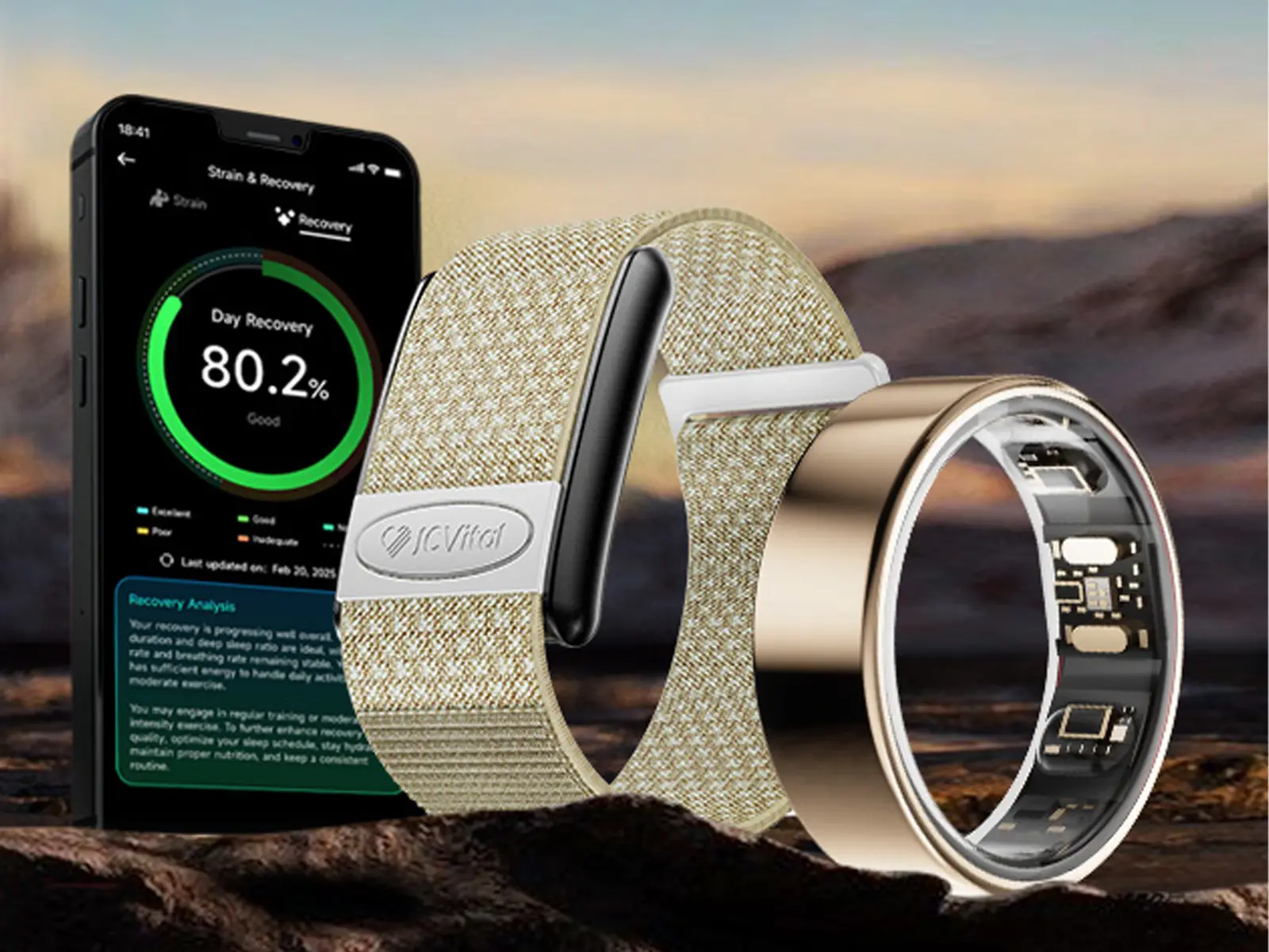
A wearable charging design should be chosen from the product's cell, enclosure, sealing target, charging current, thermal path, user workflow and certification plan—not from connector preference alone. Smart rings usually force tighter alignment and thermal constraints than bands, while bands may offer more room for contacts or connectors. Compare the complete source-to-cell path, then validate temperature, fault behavior, mechanical life and charging time on production-like hardware.
Charging Architecture Is a System Decision
Charging is often treated as an accessory decision: choose a cable, add a dock and specify a charging time. In a compact wearable, however, the charging architecture affects industrial design, waterproofing strategy, PCB area, battery stress, thermal behavior, firmware, packaging, serviceability and the experience users have every few days.
The architecture extends beyond the visible connector. It includes the upstream power source, cable or dock, contact or wireless-power interface, input protection, charger and power-path functions, battery protection, the cell, system loads and the firmware that reports state and faults. If any link in that chain is underspecified, a device can charge slowly, stop early, heat unexpectedly, reset during charging or behave differently with different adapters.
For procurement and product teams, the practical question is not “Which charging method is best?” It is “Which architecture best satisfies our product envelope, use case, compliance path and acceptance criteria with controllable manufacturing risk?” That framing should begin during architecture definition, not after the enclosure has been frozen.
Map the Source-to-Cell Power Path
A useful review starts with a block diagram that follows power from the wall adapter to the battery and records the responsibility of every stage:
- External source: adapter, USB port, power bank or dedicated base.
- Cable and dock: connector rating, cable resistance, magnet orientation, alignment features and replaceability.
- Wearable interface: exposed contacts, spring contacts, integrated USB, inductive coil or proprietary receiver.
- Input protection: reverse connection, overvoltage, electrostatic discharge and abnormal-source behavior as required by the design.
- Charge management: input-current limit, precharge, constant-current and constant-voltage control, termination, recharge, safety timer and temperature response.
- Power path: whether the system runs from the input, the battery or a managed combination while charging.
- Cell and protection: the approved cell, protection circuit, thermistor arrangement and mechanical integration.
- Firmware and indicators: charge-state reporting, faults, dock detection, LEDs, app messages and diagnostic logs.
Texas Instruments' guidance on battery-charging considerations for low-power applications highlights the relationship between small wearable form factors, charger topology and thermal performance. The same input voltage and nominal charge current can create very different board and enclosure temperatures depending on conversion method, layout and heat dissipation.
Compare the Main Wearable Charging Interfaces
| Interface | Potential advantages | Design risks | Best-fit questions |
|---|---|---|---|
| Contact pads with magnetic or spring-contact dock | Compact receiver side, efficient transfer, straightforward electrical measurement | Contact contamination, corrosion, wear, polarity, magnet force and dock tolerance | Can the contacts remain clean, aligned and protected through the target use environment? |
| Clip or cradle with pogo pins | Positive mechanical location and serviceable charger accessory | Pin travel, contact force, cosmetic marks, asymmetric insertion and mechanical fatigue | Can users place the device correctly without excessive force or ambiguity? |
| Integrated wired connector | Familiar cable ecosystem and no separate receiver coil | Enclosure opening, connector volume, sealing complexity and port wear | Does the band geometry have enough space and a defensible ingress strategy? |
| Proprietary inductive dock | No exposed electrical contacts and greater freedom for sealed surfaces | Alignment sensitivity, coil and shield volume, efficiency, heat and proprietary accessory dependence | Can the mechanical stack maintain repeatable coupling across production tolerances? |
| Standards-based wireless charging | Potential interoperability when the complete product is genuinely certified | Receiver size, coil geometry, certification scope and unsupported logo or compatibility claims | Does the target standard actually fit the device class, power level and industrial design? |
Contact charging: efficient but exposed
Contact charging can keep the wearable-side electronics compact. It is often easier to characterize electrically because the input path is directly accessible. The engineering work moves into surface finish, contact geometry, wiping action, spring force, magnet arrangement, drainage, contamination and electrochemical behavior. A dock that works on a clean engineering bench may become intermittent after sweat, skincare products, debris or repeated misalignment.
Polarity and orientation deserve explicit protection. Magnets can make an accessory feel self-aligning while still allowing an unintended contact sequence or partial engagement. Mechanical keying, electrical protection and firmware fault handling should agree on the safe behavior.
Inductive charging: sealed surfaces, tighter coupling work
Inductive power removes exposed charging conductors but adds a transmitter, receiver coil, magnetic materials, alignment features and conversion losses. Small changes in distance, tilt or lateral offset can affect power transfer and heat. Metal-rich enclosures and very small ring geometries make electromagnetic and mechanical co-design especially important.
Do not call a proprietary inductive system “Qi” merely because it transfers power wirelessly. The Wireless Power Consortium states that products may use the Qi mark only after the applicable certification process. Its certification process includes compliance and interoperability testing. Product teams should define whether they need a proprietary dock, compatibility with a standard, or formal certification, and keep those claims separate.
Match the Charger to the Cell and Thermal Envelope
The approved battery cell—not a generic battery assumption—should determine charge-voltage limit, current, precharge behavior, termination threshold and temperature limits. The cell supplier's documentation, protection design and charger configuration must agree. Copying settings from an earlier product without confirming the new cell and thermal stack creates avoidable risk.
Compact products make thermal behavior visible to the user. Charger loss, coil loss, contact resistance, battery impedance and simultaneous system load all contribute. A charger IC may regulate its own junction temperature, but that does not automatically prove that the cell, enclosure or skin-facing surface remains within the product's approved limits. TI describes functions such as battery-temperature sensing, overvoltage and overcurrent protection, thermal regulation and thermal shutdown in its overview of charger protection considerations.
A useful thermal plan measures more than the charger IC. Record input voltage, current, battery voltage, charge current, charger temperature, cell temperature and relevant enclosure-surface temperatures through the complete cycle. Repeat the measurement at representative ambient conditions, initial states of charge, system workloads, dock alignment positions and production tolerances.
Decide Whether the Device Operates While Charging
A power-path architecture can supply the system while managing battery charging. Nordic Semiconductor describes dynamic power-path management as regulating current to and from the battery according to system requirements, including operation from input power when the battery is depleted, in its PMIC system documentation.
That capability does not mean every wearable should remain fully active while charging. The product team must decide what happens to sensors, radios, displays, haptics, LEDs, storage and firmware updates. Simultaneous system load can extend charge time, change thermal behavior and complicate termination. If the device is intended to be removed for charging, disabling selected functions may create a clearer and more repeatable profile.
Document these states in the firmware requirements. Include dock detection, debounce behavior, state-of-charge reporting, completion indication, restart after a fault, recovery from an interrupted charge and behavior when a weak source is connected. Then connect the charging load back to the product's wearable power budget.
Treat the External Power Source as a Variable
The same wearable may be connected to laptops, legacy adapters, power banks and modern USB-C supplies. The dock or cable must not assume that every source offers the same current or negotiation behavior. Input-current limiting, voltage droop and cable resistance can change the apparent charging time even when the wearable hardware is unchanged.
If a dock uses USB Type-C, implement the applicable USB rules rather than treating the connector as a mechanical power socket. The USB Implementers Forum explains that USB Power Delivery builds on the USB ecosystem to provide flexible power delivery, while base USB and Type-C modes define their own source and sink behavior. Review the current USB-IF charging and Power Delivery guidance for the selected implementation and certification plan.
Validate the Complete Charging Experience
A charging test should cover the accessory, device, firmware and user interaction as one system. Bench confirmation of one charge cycle is not enough for a sourcing decision. Convert the architecture into measurable wearable acceptance criteria and define the exact units, firmware, cells, cables and sources used.
| Validation area | Representative questions | Evidence |
|---|---|---|
| Electrical | Are input limits, charge phases, termination and reverse leakage consistent? | Time-aligned voltage, current and state logs |
| Thermal | What are cell, IC and enclosure temperatures across alignment and ambient conditions? | Calibrated measurements and test setup record |
| Mechanical | Does the dock locate reliably after repeated use, contamination and tolerance variation? | Cycle, force, wear and alignment results |
| Fault handling | What happens with poor contact, wrong orientation, weak source, overtemperature or interruption? | Defined fault injection and recovery observations |
| Firmware and UX | Are charging states, completion, faults and app status understandable and accurate? | State-transition log plus UI acceptance review |
| Manufacturing | Can contact resistance, coil alignment and charger configuration be controlled in production? | End-of-line limits, fixture method and traceability plan |
| Accessory ecosystem | Which cables, adapters and replacement docks are supported? | Approved accessory matrix and labeling review |
A practical charging-validation sequence
- Freeze the approved cell, charger configuration, dock revision and firmware baseline.
- Verify the normal charge profile from defined initial battery states.
- Measure temperature and charging time with minimum, nominal and demanding supported system loads.
- Repeat across the expected source, cable and alignment combinations.
- Inject foreseeable contact, source, temperature and interruption faults.
- Run mechanical and environmental conditioning, then repeat electrical tests.
- Confirm end-of-line tests can detect the failure modes that matter.
- Record acceptance limits, sample size, instruments, firmware and unresolved deviations.
This sequence should be adapted to the product and market. It does not replace battery-supplier instructions, electrical safety work, transport testing, EMC evaluation, ingress validation or any certification applicable to the finished device and charger.
What B2B Buyers Should Put in the RFQ
- Target device format, enclosure material and sealing objective.
- Preferred contact, cradle, connector or inductive user experience—and whether it is a preference or a fixed requirement.
- Approved or target battery-cell information and required operating scenarios.
- Expected charging-time target with its starting condition and allowable source.
- Whether the device must operate, synchronize or update firmware while charging.
- Required indicators, app states, diagnostics and fault logs.
- Target markets, adapter strategy, labeling and certification responsibilities.
- Replacement-charger, packaging and spare-accessory requirements.
- Thermal, mechanical, ingress and reliability acceptance criteria.
- Golden-sample, pilot-build and production-test evidence required before approval.
These questions belong in the project definition and wearable product development process. They also help distinguish a cosmetic charger change from a deeper ODM project involving enclosure, electronics, firmware, tooling and compliance work.
Limitations and Product-Specific Verification
This guide explains general engineering decisions. It does not establish the cell type, charging method, input rating, charge time, thermal performance, waterproofing or certification status of any specific J-Style model. Those facts must be verified for the named product, charger revision, firmware and market.
Charging customization depends on product architecture, available PCB and enclosure space, cell requirements, tooling, firmware scope, certification and commercial feasibility. During evaluation, use production-representative samples and a written smart wearable sample checklist rather than inferring finished-product behavior from an early engineering prototype.
Define the Charging System Before Freezing the Enclosure
A credible wearable charging design balances compact packaging, repeatable alignment, electrical protection, cell requirements, thermal limits, firmware behavior and manufacturing control. The best interface is the one that can be explained, measured and produced under the target use conditions—not the one with the most familiar label.
If you are evaluating a smart-ring or smart-band charging concept, contact J-Style to request product information and discuss the device format, charging workflow, target markets and validation requirements. Product-specific capabilities and project scope should be confirmed before specifications or delivery commitments are made.